Group (5 people)
3 months
RC Car
2018
Lola
This project took place during the final year of my BEng degree course, prompted by a brief to design, make and race a remote control car. The car had to be 3D printed and had to operate within the relevant international standards.
The project was carried out in groups of five. Each of the team members got assigned a different area of expertise, mine being the bodywork and the frontal impact attenuator (nose cone). The other members designed the chassis, drive mechanism, steering and wheels, respectively. We then brought in our individual parts for the prototyping and testing stage.


1.
Design Objectives
Narrowing down our target audience
The objectives are to design, model and manufacture a unique radio-controlled car within a set of given parameters, outlined in the Design Specification, to bridge the gap in the market between low-end toys and high spec hobby cars.
The target market was individuals of all ages with an interest in hobby-car building, and will hopefully serve to expose more people to the advantages and possibilities associated with additive-layer manufacture (3D printing).

2.
Design Spec
Understanding our constraints
Several areas were considered when creating the general design specification for the project:
-
Sizing & Ground clearance
-
Safety compliance (EN & EU)
-
Manufacturing methods
-
Specified components
-
Ease of user assembly
-
Crash test performance needs
-
Turning circle
-
Durability
-
Weight
-
Recyclability
-
Market Appeal
-
Selling price
3.
Bodywork
Ideation


4.
Bodywork refinement
Choosing a look for our car
In order to identify the style that would bring the most desirable combination of features, all five of them were graded in a Pugh decision matrix against criteria taken from the product specification.
The Futuristic concept received the highest score. Somewhat minimalistic, we hoped it'd reduce manufacture and post-production time, while providing high robustness and a relatively low weight, as well as a very strong unique selling point due to its original design.
Several sketches were then made to inform the CAD model that was to be built.
5.
Nose cone
Calculations
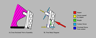
Crash test requirements
Our car had to survive a crash test at the end of the assignment, during which the car would be dropped down a 45 degree slope onto a firm obstacle. With this in mind, I performed some initial calculations (forces, impulse, duration of impact, crumple distance, etc.) to inform the design of the nose cone.
Since the impact forces weren't too high, I set to design a nose cone that would be resistant and capable of transferring the loads without breaking, rather than a replaceable crash structure.
6.
Nose cone ideation & refinement
Choosing a nose cone style
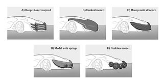
Five different concepts were developed, ranging in complexity and inventiveness. Although these were assessed in a Pugh matrix against the same criteria as the bodywork (namely lightness, robustness, design and manufacture time, aerodynamics and aesthetics). Different weighting was given to each, as the nose cone was to be designed with a stronger focus on technical functionality.
The Honeycomb structure was chosen because of its lightness and robustness, though it was expected to require slightly higher design and manufacturing times.

7.
First Prototype
CAD Modelling & First 3D Prints
The Futuristic concept chosen was adapted to ease the CAD stage, after taking into consideration the time available as well as the manufacturing constraints the 3D Printer posed. Other considerations taken when developing the model included design for assembly, manufacturing, recyclability and compliance.
With these constraints in mind, the bodywork was made modular, its subcomponents attached by means of seamless click joints for ease of assembly and disassembly. This modular design also allowed quick access to the inner electronics of the car without a need for full removal (which would entail unscrewing certain bodywork pieces from the chassis.
A first concept of the nose cone was also 3D printed though it would soon get optimized through FEA.

8.
FEA & Iteration
Optimizing the nose cone
At this point, every team member took their components and optimized them through Finite Element Analysis. In my case, I focused my time on optimizing the nose cone. Through this FEA step, the goals were to achieve the factor of safety desired, to reduce weight, improve manufacturability, and most importantly, to achieve a high dissipation of loads away from the chassis.
After 5 iterations, the nose cone's original honeycomb structure was replaced by a thinner, solid plate which transferred loads more evenly and eased the 3D printing process. The nose cone's attachment points to the chassis were reinforced and a spring-like structure was added behind the main plate to aid impact absorption.
All in all, the nose cone saw a 40% reduction in weight and a 50% reduction in manufacturing time, as well as the desired load dissipation pattern.
9.
Second
Prototype
Final touches
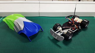
After all the components of the car were optimized, a second and final prototype was printed.
The bodywork saw a decrease in the the amount of components, whilst the new, optimized nose cone design was incorporated (please note, the first iteration nose cone is shown on the image on the left — the new one had not yet been printed when this image was taken!).
Unfortunately, the 3D printing workshop ran out of grey filament so our car ended up with this somewhat unfortunate tri-coloured look! But the car was ready to be tested.

10.
Crash test & Write-up
Moment of truth
Our final prototype successfully passed its crash test and was fully funcitonal by the time our 3-month project came to a close. We created some final renders and set out to write an extensive report on the process.
Full technical drawings were created and handed in an part of the tech pack required for our assignment. A full business model was also put forward, including market, cost and SWOT analysis, benchmarking exercises and reflections on team organisation and structure.
Final product
Lola: the RC Car of the futurists!
We called her Lola because she was definitely a show girl — the whole group was extremely pleased with the result and grateful to each other for a wonderful collaboration.
To this day, this group project has set the standard of what working as an organised and competent team should look like. I consider myself very lucky to have had Andrew, Ben, Sam and Max by my side.
